So, the switch in question is divided into three parts, for controlling three different lights. One of these is an outlet located close to the ceiling, just above a cupboard.
The most elegant solution would be to hook this outlet up to the device controlling the Nexa switches. Power comes on, send signal for turning on the Nexa switches. Power dissapears, send signal for turning off the Nexa switches.
This requires us to detect the power off from the outlet and send the OFF signal before the power is totally gone.
Using a 9V (more like 12V) 200 mA AC adaptor and hooking the outputs of this circuit to a atiny13A MCU and a standard
Itead 433 MHz radio, using the attiny13a to detect when the voltage dropped from 'V detect' the following were obtained:
R1 360 Ohm
R2 180 Ohm
D1 1N4001
C1 1000uF, 50V
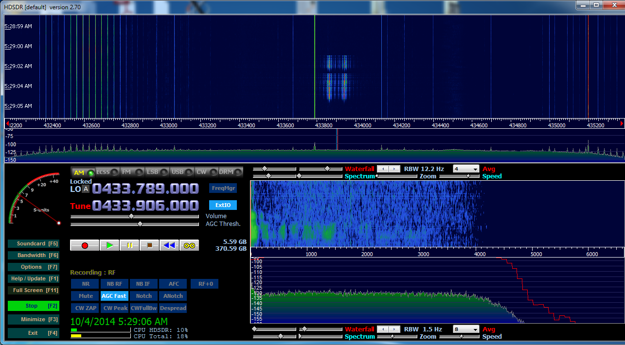
Radio operates 650 ms after 'V detect' goes low.
Since the Nexa transmission requires ca. 400 ms, no modifications to this setup were necessary. The NEXA protocol is described
here.
The attiny13A is programmed to send the ON signal when the power comes on. It then enters a loop waiting for the voltage indicator to drop and then sends the OFF signal.
Voltage drops at '1', radio stops sending at '2'.
 /*
  * Lysbryter.c
  *
  * Created: 4/6/2014 12:11:38 PM
  * Author: hwa
  */
 #define F_CPU 8000000
 #include <avr/io.h>
 #include <util/delay.h>
 #define RPORT PINB0
 void send_signal(uint32_t ID, uint8_t GRP, uint8_t ON, uint8_t UNIT);
 void pulse();
 void pulse()
 {
      PORTB |= (1<<RPORT);
      _delay_us(230);
      PORTB &= ~(1<<RPORT);
 }
 // delays determining '0' or '1'
 #define SHORTDELAY 400
 #define LONGDELAY 1420
 void send_signal(uint32_t ID, uint8_t GRP, uint8_t ON, uint8_t UNIT)
 {
      uint16_t t1,t2;
      t1 = (ID>>10);
      t2 = (ID<<6);
      if (GRP==1)
      {
           t2 |=1<<5; //Group command
      }
      if (ON==1)
      {
           t2 |= 1<<4; //ON
      }
      // ORin UNIT
      t2 = t2 | (UNIT & 0x0F);
      pulse();
      _delay_us(1000);
      _delay_us(1000);
      _delay_us(825);
      for (int i =15;i>=0;i--)
      {
           if (((t1) & (1 << i)) == 0)//Console::WriteLine("0");
           {
                pulse();
                _delay_us(SHORTDELAY);
                pulse();
                _delay_us(LONGDELAY);
           }
           else//Console::WriteLine("1");
           {
                pulse();
                _delay_us(LONGDELAY);
                pulse();
                _delay_us(SHORTDELAY);
           }
      }
      for (int i =15;i>=0;i--)
      {
           if (((t2) & (1 << i)) == 0)//Console::WriteLine("0");
           {
                pulse();
                _delay_us(SHORTDELAY);
                pulse();
                _delay_us(LONGDELAY);
           }
           else//Console::WriteLine("1");
           {
                pulse();
                _delay_us(LONGDELAY);
                pulse();
                _delay_us(SHORTDELAY);
           }
      }
      pulse();
 }
 int main(void)
 {
      int nopower = 0;
      //DDRB &= ~(1<<PINB4);
      DDRB=0;
      DDRB |= (1<<PINB0); // output
      PORTB &= ~(1<<PINB0); //off
      //PORTB &= ~(1<<PINB4); //pullup
      _delay_ms(100);
      // send turn on signal to the group
      for (int i =0;i<7;i++)
      {
           send_signal(0x280526, 1,1,0);
           _delay_ms(11);
      }
   while(1)
   {
            if(bit_is_clear(PINB, PINB4))
            {
                nopower = 1;
           }
           if (nopower==1)
           {
                for (int i =0;i<7;i++)
                {
                     send_signal(0x280526, 1, 0, 0); //off
                     _delay_ms(11);
                }
           }
      }
 }
Looking at the source code it is apparent that one could have used a function 'calculate_signalstring' which returned the bits to send thus eliminating the need for recomputation each time 'send_signal' was executed. '0x280526' is the ID code for my Nexa remote.
 |
| Signal from the ATtiny13A |
It did appear that the reciever were forgiving with the exact pulsewidth and pulse delays in the sequence. Two initial adjustments were all it took to make the reciever accept the signal.
 |
| Signal from the NEXA remote |
Looking at the last six bits of these patterns it is apparent that the attiny13A is sending the group/off signal while the remote sends the unit 1 on signal.


