Friday, January 22, 2016

Obtaining the external WAN IP address from a Netgear WNR2000v5

Earlier I used a DNS service in order to get the IP address of my internet connection. I used some free ones, and they worked very well. Until they didn't work.

Then I used an external server, like duckduckgo.com, utilizing the computer, with python, already running in my house. Something like:

adr = "https://duckduckgo.com/?q=what+is+my+ip&ia=answer"
req = urllib2.Request(adr)
res = urllib2.urlopen(req)
data = res.read()
res.close()
...
p = re.compile('\"Answer\":"Your IP address is (\d*).(\d*).(\d*).(\d*) in')
m = p.search(data)
...
current_ip = (m.groups()[0], m.groups()[1], m.groups()[2], m.groups()[3])
...

This data were then uploaded to a know web page if it were different from the previous address.

And that worked great, until I occasionally started to use a VPN service on the machine running the script. Then duckduckgo.com returned the IP address of my VPN, which would not forward my ssh logins to my home.


So I checked my router, Netgear WNR2000v5, and it returned the IP address as expected. But only from the page "RST_conn_status.htm". It would also return "Access denied" for the first login attempt if someone had logged in to the router for another machine. And it required a username/password.

The script then became:

username='admin'
password='password'
adr = 'http://10.0.0.1/RST_conn_status.htm'
try:  #if someone else logged in to the router we get access denied the first time
 req = urllib2.Request(adr)
 base64string = base64.encodestring('%s:%s'%(username, password)).replace('\n', '')
 req.add_header("Authorization", "Basic %s" % base64string)   
 res = urllib2.urlopen(req)
except:
 time.sleep(1)
req = urllib2.Request(adr)
base64string = base64.encodestring('%s:%s' % (username, password)).replace('\n', '')
req.add_header("Authorization", "Basic %s" % base64string)   
res = urllib2.urlopen(req)
time.sleep(1)
data = res.read()
res.close()
...
p = re.compile('var info_get_wanip=\"(\d*).(\d*).(\d*).(\d*)\";')
m = p.search(data)
...
current_ip = (m.groups()[0], m.groups()[1], m.groups()[2], m.groups()[3])
...


Saturday, October 4, 2014

Studying the TPMS signals from Subaru a.k.a. Schrader signals

1) Observing the car at standstill produced no signals. Even after driving.

Data collection: So far windows and HDSDR have been used. SDR# is not available to me, Neither a portable coputer with gnuradio. Recordings produced files that ended like this: 433789kHz_RF.wav Stereosignals in Audacity with something that looked like quadrature detection. Is this the I/Q?

2) While driving, an some signals were registered, approx one every 14 seconds.


The first part of the signal is constant, the second part varies.  48 bits. 8 first bits a short pulse. The second part is closer to the resonance frequency. Driving on, I never manage to observe this signal again. Maybe a local, exterior signal?


3) After some fiddeling with parameters, some other signal are observed.

I first processed these data with a low pass filter, then a normalization. Not wise, a repeating signal is also observed without the initial low pass filter:


Eight groups of packets, separated by 100 ms.


The packets are not yet analyzed, could this signal shape indicate FSK? Seems to be three different pulse lengths in the packet.  Like Jared Boon is taking about here.

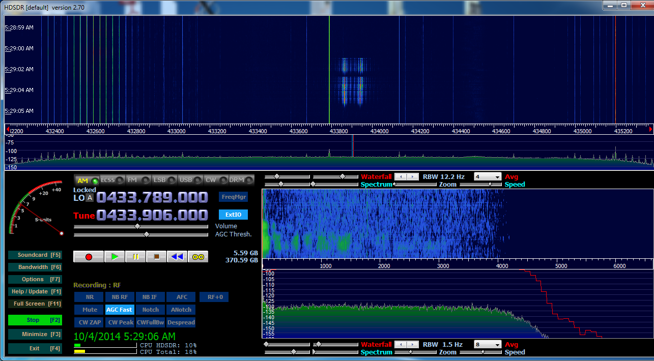
Screendump from HDSDR:


Monday, September 29, 2014

Decoding Biltema Weatherstation 84086 / sensor 84056


This weather station is sold with one remote sensor and a base station capable of monitoring airpressure. It also have a radio controlled clock.

The remote sensor is capable of measuring temperature and pressure and broadcast this information on the 433 MHz band.

Using a 433 MHz receiver together with a logic analyzer several things could be learned:

The sensor transmit 20 bits of information starting with a 1.45 ms pulse followed by 1.50 ms silence. Pulses 2.16 ms long followed by 0.77 ms silence is '1', and 0.70 ms pulses followed by 2.23 ms silence is representing '0'.


Channel 2, -16.6C, 20% humidity

Several different measurements obtained with varying temperatures and constant humidity (36% (0b100100)) showed that the sensor transmitted the humidity in the seven last bits of the transmission.

The last seven bits is arranged in the following fashion: bit 1, 0 , 6, 5, 4, 3 and 2.

Yeah, and after some googling I found that the decoded signals were presented at telldus.com.

In the following table this decoding is used with the exception of me rotating the bitorder.


Tuesday, April 8, 2014

Turning NEXA recievers on and off from the light switch

So, the switch in question is divided into three parts, for controlling three different lights. One of these is an outlet located close to the ceiling, just above a cupboard.

The most elegant solution would be to hook this outlet up to the device controlling the Nexa switches. Power comes on, send signal for turning on the Nexa switches. Power dissapears, send signal for turning off the Nexa switches.

This requires us to detect the power off from the outlet and send the OFF signal before the power is totally gone.


Using a 9V (more like 12V) 200 mA AC adaptor and hooking the outputs of this circuit to a atiny13A MCU and a standard Itead 433 MHz radio, using the attiny13a to detect when the voltage dropped from 'V detect' the following were obtained:

R1 360 Ohm
R2 180 Ohm
D1 1N4001
C1  1000uF, 50V
Radio operates 650 ms after 'V detect' goes low.

Since the Nexa transmission requires ca. 400 ms, no modifications to this setup were necessary. The NEXA protocol is described here.


The attiny13A is programmed to send the ON signal when the power comes on. It then enters a loop waiting for the voltage indicator to drop and then sends the OFF signal.


Voltage drops at '1', radio stops sending at '2'.

 /*
  * Lysbryter.c
  *
  * Created: 4/6/2014 12:11:38 PM
  * Author: hwa
  */  
 #define F_CPU 8000000
 #include <avr/io.h>
 #include <util/delay.h>
 #define RPORT PINB0
 void send_signal(uint32_t ID, uint8_t GRP, uint8_t ON, uint8_t UNIT);
 void pulse();
 void pulse()
 {
      PORTB |= (1<<RPORT);
      _delay_us(230);
      PORTB &= ~(1<<RPORT);
 }
 // delays determining '0' or '1'
 #define SHORTDELAY 400
 #define LONGDELAY 1420
 void send_signal(uint32_t ID, uint8_t GRP, uint8_t ON, uint8_t UNIT)
 {
      uint16_t t1,t2;
      t1 = (ID>>10);
      t2 = (ID<<6);
      if (GRP==1)
      {
           t2 |=1<<5; //Group command
      }
      if (ON==1)
      {
           t2 |= 1<<4; //ON
      }
      // ORin UNIT
      t2 = t2 | (UNIT & 0x0F);
      pulse();
      _delay_us(1000);
      _delay_us(1000);
      _delay_us(825);
      for (int i =15;i>=0;i--)
      {
           if (((t1) & (1 << i)) == 0)//Console::WriteLine("0");
           {
                pulse();
                _delay_us(SHORTDELAY);
                pulse();
                _delay_us(LONGDELAY);
           }                
           else//Console::WriteLine("1");
           {
                pulse();
                _delay_us(LONGDELAY);
                pulse();
                _delay_us(SHORTDELAY);
           }
      }
      for (int i =15;i>=0;i--)
      {
           if (((t2) & (1 << i)) == 0)//Console::WriteLine("0");
           {
                pulse();
                _delay_us(SHORTDELAY);
                pulse();
                _delay_us(LONGDELAY);
           }                
           else//Console::WriteLine("1");
           {
                pulse();
                _delay_us(LONGDELAY);
                pulse();
                _delay_us(SHORTDELAY);
           }
      }
      pulse();
 }
 int main(void)
 {
      int nopower = 0;
      //DDRB &= ~(1<<PINB4);
      DDRB=0;
      DDRB |= (1<<PINB0); // output
      PORTB &= ~(1<<PINB0); //off
      //PORTB &= ~(1<<PINB4); //pullup
      _delay_ms(100);
      // send turn on signal to the group
      for (int i =0;i<7;i++)
      {
           send_signal(0x280526, 1,1,0);
           _delay_ms(11);
      }
   while(1)
   {
            if(bit_is_clear(PINB, PINB4))  
            {
                nopower = 1;  
           }          
           if (nopower==1)
           {
                for (int i =0;i<7;i++)
                {
                     send_signal(0x280526, 1, 0, 0); //off
                     _delay_ms(11);
                }
           }
      }
 }

Looking at the source code it is apparent that one could have used a function 'calculate_signalstring' which returned the bits to send thus eliminating the need for recomputation each time 'send_signal' was executed. '0x280526' is the ID code for my Nexa remote.


Signal from the ATtiny13A
It did appear that the reciever were forgiving with the exact pulsewidth and pulse delays in the sequence. Two initial adjustments were all it took to make the reciever accept the signal.
Signal from the NEXA remote
Looking at the last six bits of these patterns it is apparent that the attiny13A is sending the group/off signal while the remote sends the unit 1 on signal.

Thursday, December 26, 2013

More on observing the 433MHz band, Nexus IW004

One of the Christmas gifts in the family this year was a weather station, "Nexus IW004 / 36-5136". Some 'googling' of the brand got me to one of the local gadget stores in the region, Clas Ohlson. It is capable of measuring indoor and outdoor temperature and humidity, air pressure and the date. It also predicts the upcoming weather based on these data. The outdoor unit includes a sensor with mounting possibilities attached to the unit with a 1 meter wire.

Analysing the data with a 433 MHz receiver unit and a logic analyser showed a burst of twelve identical signals, 3.9 ms apart, for each reading of outdoor status. For channel 1 these bursts were located 56.95 seconds apart. For channel 2, 67.05 seconds and for channel 3 84.97 seconds apart.

Each pulse is 0.47 ms wide, with 1.98 ms separating 'ones' and 0.99 ms separating 'zeros'. The last pulse in a 'burst' is narrower, 0.25 ms wide.


Using this information and by varying the environmental parameters the following table could be compiled:


bit  1 - 10  Sensor ID and battery status(?)
bit 11 - 12  Channel ID
bit 13 - 24  Temperature * 10 in two's complement notation
bit 25 - 28  Always 1
bit 29 - 36  Humidity


Something also happens in bit 3 - 7 when the channel changes on the outdoor sensor.

Friday, July 26, 2013

Using the Nexa remote together with a tellstick device

One of my Nexa switches is operated programmaticly from a computer via a tellstick. Whenever I want to control this device manually I will log in to the computer and issue the proper commands to operate the switch. However, not everybody finds this procedure acceptable so I needed a way to operate the switch both from the tellstick and from a Nexa remote.

First I reprogrammed the Nexa switch to accept the Nexa remote.

Then, by using the hard- and software described in decoding-new-nexa-protocol I could extract the ID code sent from the Nexa remote. This ID code could be directly entered into the "/etc/tellstick.conf" file and after a restart of the tellstick daemon the switch were operable by both the Nexa remote and the tellstick.

Tuesday, May 28, 2013

Using a MCE remote control with mythtv / xbmc


No lircd please.

After five years of mythtv 0.19 / xbmc (no udates of any kind during that time) and numerous restarts of lirc I got myself a new remote with an usb reciever, "MCE remote". A remote that shows up directly in the /dev/input directory of ubuntu 12.04. In addition to some standard buttons it also got a built in mouse. If one presses and holds down one of the numeric buttons it first emit a digit and then, after a while, emit a backspace and a character. E.g: Holding down "2" gives "2", delay, "<bs>A", delay, <bs>B, etc.

All very handy, but in the end I will probably use the reciever with my learning remote control wich also controls the amplifier and other stuff. 


It was bought under the brand name "Fractal design", but as ubuntu concerns this is the important stuff:
(since ubuntu 12.04 lists this device in /dev/input/by-id it is easy to locate, otherwise one could plug/unplug and look in the /dev/input/ directory)

sudo udevadm info -a --name=/dev/input/by-id/usb-Cypress_Cypress_USB_Keyboard-event-mouse 

Udevadm info starts with the device specified by the devpath and then
walks up the chain of parent devices. It prints for every device
found, all possible attributes in the udev rules key format.
A rule to match, can be composed by the attributes of the device
and the attributes from one single parent device.

  looking at device '/devices/pci0000:00/0000:00:02.0/usb3/3-1/3-1:1.0/input/input2/event2':
    KERNEL=="event2"
    SUBSYSTEM=="input"
    DRIVER==""

  looking at parent device '/devices/pci0000:00/0000:00:02.0/usb3/3-1/3-1:1.0/input/input2':
    KERNELS=="input2"
    SUBSYSTEMS=="input"
    DRIVERS==""
    ATTRS{name}=="Cypress Cypress USB Keyboard"
    ATTRS{phys}=="usb-0000:00:02.0-1/input0"
    ATTRS{uniq}==""
    ATTRS{properties}=="0"

  looking at parent device '/devices/pci0000:00/0000:00:02.0/usb3/3-1/3-1:1.0':
    KERNELS=="3-1:1.0"
    SUBSYSTEMS=="usb"
    DRIVERS=="usbhid"
    ATTRS{bInterfaceClass}=="03"
    ATTRS{bInterfaceSubClass}=="01"
    ATTRS{bInterfaceProtocol}=="01"
    ATTRS{bNumEndpoints}=="01"
    ATTRS{supports_autosuspend}=="1"
    ATTRS{bAlternateSetting}==" 0"
    ATTRS{bInterfaceNumber}=="00"

  looking at parent device '/devices/pci0000:00/0000:00:02.0/usb3/3-1':
    KERNELS=="3-1"
    SUBSYSTEMS=="usb"
    DRIVERS=="usb"
    ATTRS{bDeviceSubClass}=="00"
    ATTRS{bDeviceProtocol}=="00"
    ATTRS{devpath}=="1"
    ATTRS{idVendor}=="04b4"
    ATTRS{speed}=="1.5"
    ATTRS{bNumInterfaces}==" 1"
    ATTRS{bConfigurationValue}=="1"
    ATTRS{bMaxPacketSize0}=="8"
    ATTRS{busnum}=="3"
    ATTRS{devnum}=="2"
    ATTRS{configuration}==""
    ATTRS{bMaxPower}==" 98mA"
    ATTRS{authorized}=="1"
    ATTRS{bmAttributes}=="a0"
    ATTRS{bNumConfigurations}=="1"
    ATTRS{maxchild}=="0"
    ATTRS{bcdDevice}=="0100"
    ATTRS{avoid_reset_quirk}=="0"
    ATTRS{quirks}=="0x0"
    ATTRS{version}==" 1.10"
    ATTRS{urbnum}=="12"
    ATTRS{manufacturer}=="Cypress"
    ATTRS{removable}=="unknown"
    ATTRS{idProduct}=="0100"
    ATTRS{bDeviceClass}=="00"
    ATTRS{product}=="Cypress USB Keyboard"

In order to remap the remote keys we have to write a keymaps file and run this when the usb reciever are plugged into the system. A great "howto" on this is in writing udev rules. As shown by the '/dev/by-id' contents, the remote control is two units; the mouse part and the rest. The difference between these are the 'KERNEL==' attribute. Since one can use info from the device itself and one of the parent devices I used this rule:

SUBSYSTEM=="input", KERNEL=="event*", ATTRS{idVendor}=="04b4", ATTRS{idProduct}=="0100",  RUN+="/bin/sh -c 'echo $name >> /tmp/test.udev"
SUBSYSTEM=="input", KERNEL=="event*", ATTRS{idVendor}=="04b4", ATTRS{idProduct}=="0100",  RUN+="keymap $name cypressusb"

This is the method I use to convince myself that the udev rules are hit. Just check the '/tmp/test.udev' for which devices that match the rule. '/lib/udev/keymap device keymapfile' (where 'keymapfile' is located in /lib/udev/keymaps/ updates the keymap of the device). To simulate adding devices use

sudo udevadm trigger


'ir-keytable' may be used to check the keycodes emitted from the remote:

#From ir-keytable -t -d /dev/input/by-id/usb-Cypress_Cypress_USB_Keyboard-event-mouse

#Pressing buttons from top left across to the right and down

700e0 KEY_LEFTCTRL (0x001d) 
70015 KEY_R (0x0013)

c00b7 KEY_STOPCD (0x00a6)

700e2 KEY_LEFTALT (0x0038)
7003d KEY_F4 (0x003e)
**
700e0 KEY_LEFTCTRL (0x001d)
70005 KEY_LEFT (0x0069)

700e0 KEY_LEFTCTRL (0x001d)
700e1 KEY_LEFTSHIFT (0x002a)
70013 KEY_P (0x0019)

700e0 KEY_LEFTCTRL (0x001d)
700e1 KEY_LEFTSHIFT (0x002a)
70005 KEY_LEFT (0x0069)
**
700e0 KEY_LEFTCTRL (0x001d)
700e1 KEY_LEFTSHIFT (0x002a)
70005 KEY_LEFT (0x0069)

700e0 KEY_LEFTCTRL (0x001d)
70013 KEY_P (0x0019)

700e0 KEY_LEFTCTRL (0x001d)
700e1 KEY_LEFTSHIFT (0x002a)
70009 KEY_RIGHT (0x006a)
**

700e0 KEY_LEFTCTRL (0x001d)
700e1 KEY_LEFTSHIFT (0x002a)
70010 KEY_M (0x0032)

700e2 KEY_LEFTALT (0x0038)
700e3 KEY_LEFTMETA (0x007d)
70028 KEY_ENTER (0x001c)

700e0 KEY_LEFTCTRL (0x001d)
7000a KEY_G (0x0022)
**
70028 KEY_ENTER (0x001c)

7002a KEY_BACKSPACE (0x000e)

70050   KEY_LEFT
70052   KEY_UP
7004f   KEY_RIGHT
70051   KEY_DOWN

then the mouse buttons 

left mouse btn  90001  BTN_MOUSE (0x0110)
right mouse btn 90002  BTN_RIGHT (0x0111)

and joystick
and continuing...

RecTV
700e0   KEY_LEFTCTRL
70012   KEY_O

Vol+
70043   KEY_F10
Vol-
70042   KEY_F9

Ch/Pg+
7004b   KEY_PAGEUP
Ch/Pg-
7004e   KEY_PAGEDOWN

LiveTV
700e0   KEY_LEFTCTRL
70017   KEY_T
**

S1   c0223  KEY_HOMEPAGE
S2   c022a  KEY_BOOKMARKS
mute 70041  KEY_F8
S3   c0224  KEY_BACK
S4   c0225  KEY_FORWARD

red     700e0  KEY_LEFTCTRL
        700e1  KEY_LEFTSHIFT
        70017  KEY_T
green   700e0  KEY_LEFTCTRL
        70008  KEY_E
yellow  700e0  KEY_LEFTCTRL
        7000c  KEY_I
blue    700e0  KEY_LEFTCTRL
        70010  KEY_M

the numeric keys, and finally...;
clear   7002a  KEY_BACKSPACE (0x000e)
enter  70028 KEY_ENTER (0x001c)

The remote dublicates the keycodes sent from the "back" and "clear" buttons and also the "ok" and "enter" buttons.

Mythtv uses <ESC> as back key, but I don't want to reassign the 'back' key on the remote from backspace, it could be needed. Therefore the first iteration of the keymap would be to reassign left and right mouse button to OK and ESC.

/lib/udev/keymaps/cypressusb 
0x90001  OK     # left mouse btn -> OK
0x90002  ESC    # right mouse btn -> ESC